Whatever convention is used to construct the Data Flow Diagram, all DFDs are composed of the following components:
EXTERNAL ENTITIES ON A DFD
External entities are also known as terminators, sources/sinks, and actors. External entities define the sources and destinations of information entering and leaving the system. An external entity can be a person, system, or organization that has pre-defined behaviour.
External entities are mandatory on context diagrams but optional on data flow diagrams.
Description of External Entities
External entities are components that interact with a business process on the DFD but fall outside of the boundaries of the DFD.
External entities can be:
· initiators of data (i.e., spontaneous generators) flowing into the business process,
· end recipients of data (i.e., data sinks) flowing from the business process.
Examples
Examples of external entities include:
· End User,
· Purchasing Department,
· Inventory System.
Drawing External Entities on a DFD
Place external entities on the diagram with all data flows.
To reduce the visual complexity of the drawing, an external entity can be used more than once on the same DFD. Draw a diagonal line across the lower-left corner of the external entity square to indicate another occurrence of the external entity elsewhere on the same DFD.
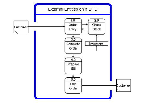
Document External Entities
Provide a description of external entities to support the DFD.
FLOWS
Definition
Flows define the interfaces between the components within the system, and the system and its external components.
Types of Flows
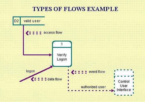
Flows that transport data around the data flow diagram are called data flows.
Description of Data Flows
Data flows are the pipelines through which data are transmitted between any two components on a DFD. The composition of data is known and defined in a data dictionary.
A data flow is also called a data flow vector.
Examples of data flows are:
· purchase order,
· customer profile,
· account number,
· product.
Naming Data Flows
Data flows must be given a name that describes the content of the data being transmitted and a description of the data flow listing the data elements. For example:
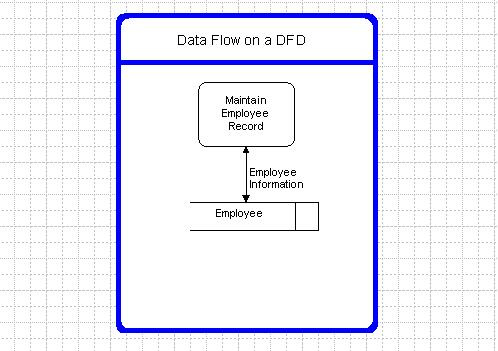
Data Flow Name: Employee Info,
Description: Information stored about an employee,
Data elements: Employee Name,
Employee Date of Birth,
Employee ID.
Bi-Directional Data Flows
Bi-directional data flows are used only when the information flowing in each direction is identical.
Data Flows with the Same Name
Multiple data flows can have the same name on a DFD. When this occurs, the data transmitted in all of the flows with the same name must be identical.
Complex Data Flows
Data flows are described as complex when there is more than one data flow going in the same direction between any two entities.
Name the complex data flow to encompass the contents of all the data flowing along the pipeline.
Trivial Data Flows
DFDs do not show trivial (relative to the specification of functional requirements) flows, such as error messages, keys for retrieving data from a data store, or data store updating instructions.
Guidelines for Drawing Data Flows on a DFD
Connect the data flows from/to external entities to/from business processes within the boundary of the DFD.
Connect internal business processes to data stores and other internal processes with appropriate data flows.
Label all data flows with care for they indicate the interface requirements for a process. Use descriptive names for labelling data flows.
Ensure that all flows to external entities on lower level diagrams balance with data flows from external entities on upper level diagrams. In other words, a new data flow cannot be created at a lower level if it was not identified on an upper level diagram.
Double-headed data flows are permitted when the data flowing in both directions are identical.
Data flows from/to external entities to/from data stores are not permitted. All data must flow through a process.
Be careful not to produce long names for complex data flows.
As a rule of thumb, a DFD component (process, data store, or external entity) should not have more than seven data flows connected to it.
Flows that access stored data are called access flows.
Flows that are used to synchronize the system control flow and do not require data are called event flows. Common uses include starting, stopping, and changing the system status. Event flows are also known as control flows.
Flows can be continuous or discrete. A discrete flow is only present for an instant of time. A continuous flow persists over time.
Types of Flows Example:
Guidelines
A data flow name should be a singular noun phrase (e.g., delivery list, customer information, credit limit).
Naming access flows is optional.
An event flow name should be a singular verb or noun phrase (e.g., start, stop, item available, processing complete).
If a data flow contains multiple attributes (i.e., data elements), an attribute list should be provided.
STORES
Definition
Stores represent information (i.e., data or control) at rest. Stores are used when different processes need to share information but are active at different times. Information can be written to a store and read from a store.
Types of Stores
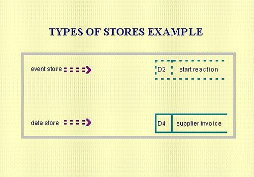
Stores that contain data are called data stores.
DATA STORES ON A DFD
Identifying Data Stores
Data stores are usually derived from the entities in an entity-relationship diagram.
Creation of Data Stores
Data stores are created to store information for later use. They represent data that is temporarily at rest between processes. For example, a data store is needed to store data that is generated on a daily basis but is required for a process that runs weekly.
Local and Shared Data Stores
Local data stores are data stores whose accesses are contained completely within the boundary of a DFD.
A data store crossing the boundary of a DFD process indicates that it is shared by processes on another DFD.
Drawing Data Stores on a DFD
A data store can be drawn on the same DFD more than once to reduce the visual complexity of the drawing. An extra vertical bar is drawn in the duplicated data stores to indicate that it appears elsewhere on the same diagram.
Stores that contain status or control information are called event stores. Event stores are used to save events that have occurred but have not yet been used. Unlike a data store, an event store has behaviour associated with it which is not apparent when looking at the data flow diagram. If the system accesses an event store and the event has not occurred, the system will be suspended until the event occurs. Once an event has occurred, accessing it will remove it from the event store.
Types of Stores Example
Guidelines
The data stores on the data flow diagram map to the entities on the entity-relationship diagram.
Minimize the use of event stores on the DFD. Try using flags instead.
PROCESSES
Definition
Processes are also known as data transforms. Processes transform input flows into output flows in a defined manner.
A process is a distinct activity (or set of activities) described by its inputs and outputs. A process describes a unique behaviour that has a beginning and an end. A process is performed repeatedly.
Types of Processes
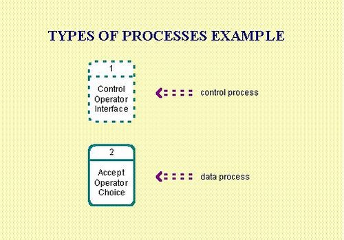
A data process transforms input data into output data. Data processes act directly on data, either from flows or stores. They represent the functionality of the system.
A control process transforms input events into output events and is used on a data flow diagram to indicate the presence of a state transition diagram. Control processes cannot transform data but can control processes that do. A state transition diagram describes the behaviour of the control process.
Types of Processes Example
Guidelines
A process name and number must be unique. A process can only exist once on a data flow diagram.
A process must have at least one input and one output. In other words, a process is asked (i.e., triggered) to do something and then must deliver (i.e., respond).
A data process cannot input or output discrete event flows (i.e., a data process should not control the system, it should do the work).
A control process cannot input or output data flows (i.e., a control process should control the system, not do the work).
A process name should start with an active verb (e.g., Produce Items, Control Production).
A process exists to do something (i.e., transform input flows into output flows), therefore a process must have an incoming set of requirements to which it must conform.
An nth-level (i.e., next level of detail) data flow diagram must describe its parent process. An nth-level data flow diagram is a decomposition of its parent process and cannot introduce new functionality.
Notation
There are several conventions used to depict the DFD.
NOTATION ON A DATA FLOW DIAGRAM
Gane and Sarson
The notation described below and used in this technique was popularized by Gane and Sarson:
· Round-ended rectangles represent processes.
· Squares identify external entities.
· Arrows indicate flows.
· Open-ended rectangles identify stores.
· Diagonal line across the lower-left corner of an external entity square indicates it appears elsewhere on the same DFD.
· Extra diagonal line on a data store rectangle indicates it appears elsewhere on the same DFD.
· Double-headed arrow indicates the same data flowing in both directions.
Yourdon, DeMarco, and Others
Another notation popularized by Yourdon, DeMarco, and others is described below:
· Circles represent processes.
· Squares identify external entities.
· Arrows indicate flows.
· Rectangles open on both ends identify stores.
Extensions
To support the use of DFDs in describing how systems respond to events, the notation has been extended to include the control-oriented information typically needed to describe real-time systems. The widely adopted convention is to represent the control components using dashed lines. The extensions apply to both notations described above.
No comments:
Post a Comment