Use a Sequence Diagram to communicate interactions in the object model or as a tool to help abstract behaviours to simplify the model.
A sequence diagram illustrates the sequence of events in a use case. That is, it shows the objects interacting. Creating the diagrams allows a designer to ensure that the object model is complete. The sequence diagram:
- illustrates the actions and sequence, with a granularity (detailed, high level) depending on the nature of the action (e.g., complexity) and stage of life cycle.
- provides an effective way to understand if the object interactions can fulfill the use case. That is, if the objects involved have sufficient attributes and behaviours to complete the use case.
- serves as documentation for the messages required.
Structure
There are many notations used to represent this type of diagram. One of the most common uses a simple notation of vertical lines and horizontal arrows.
The vertical axis of the sequence diagram represents time, which increases from top to bottom. Stated otherwise, events are chronologically ordered from top to bottom.
A limitation of sequence diagrams is that they emphasize sequential, synchronous message passing. Consequently, they do not show asynchronous message passing, timing issues or other concurrent activities well.
Generic Diagram
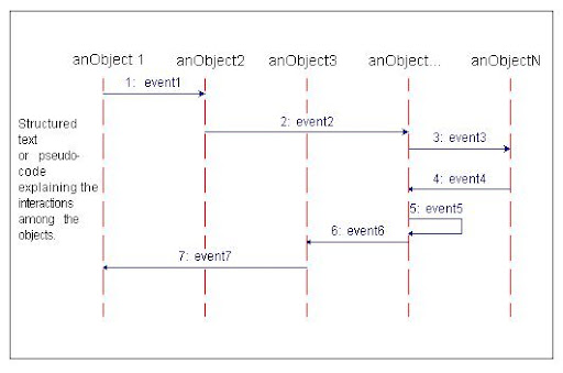
An example of a generalized structure for a sequence diagram is shown in the diagram. In the general example the objects are anObject1, anObject2, anObject3, anObject ..., and anObjectN. The example messages passed between objects are labeled 1: event1, 2: event2, 3: event3, etc., where the number prefixing the message name indicates its sequence order. For example, anObject 1 first sends anObject 2 the message event1, anObject2 in turn sends anObject... the message event2, and so on.
Method
Represent objects (that is, actors in use cases) in a sequence diagram by labeled vertical lines.
Represent messages passed (events in use cases) between objects by labeled horizontal arrows that start with the sending column (object/actor) and end with the receiving column.
Indicate messages that objects send to themselves as loops (e.g., message event5).
Identify the key classes and operations in the use case. Reduce the control flow of the use case to structured text.
For each use case identify the stimulus that initiates the event and the object to which the stimulus is sent. Identify whether that object can respond directly, or must collaborate with another object to respond. If the object collaborates, draw a labeled horizontal line to the object with which it collaborates.
Continue until all actions necessary to complete the use case are included.
An optional text description may be included with the sequence diagram for structured text or pseudo-code to explain the object interactions.
The example use case for the MTC Travel Agency requirements example is illustrated in the sequence diagram.
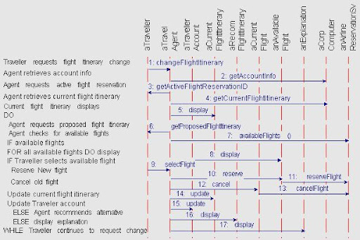
Reading the Diagram
The example use case sequence diagram can be read chronologically from top to bottom. As the structured text at the upper left indicates, the use case begins when the Traveller requests flight itinerary change. This is reflected in the graphic part of the sequence diagram by the first event, changeFlightItinerary, which aTraveller sends to aTravelAgent object. As a consequence the Travel Agent retrieves account information for aTraveller, which is shown by the second event, getTravellerAccount, which aTravelAgent sends to aCorpComputingSys.
The rest of the use case proceeds similarly, although later sequences introduce some simple logical control flow constructs, including a nested IF-THEN-ELSE statement and a DO-WHILE loop. It is a common practice to use pseudo-code in use cases in order to clarify the sequencing logic.
No comments:
Post a Comment